The Microphone
In the series about rock music hardware, we take a look at the microphone.
Technical and musical greetings from
Kurt Starlit
- aka CykelKurt
This series includes:
Latest update: 2016.June.21
--------------------------------------------------
The Microphone
The purpose of a microphone is to convert sound into voltage. The microphone converts (changes) an ancoustic signal (a sound) into an electric signal (a voltage.
Through a long period of development (hundred years or more) experimentation with different types of microphones has been carried out, e.g. ribbon microphone, dynamic microphone, condenser microphone, electret microphone, carbon microphone and crystal microphone, but common to them all is that they convert sound into voltage.
--------------------------------------------------
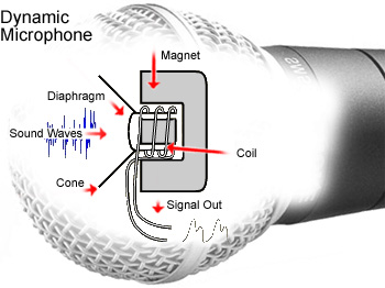
Dynamic Microphone
The most common microphone is the dynamic. It is similar in many ways to a "reversed" speaker, meaning, that it consists of a magnet and a diaphragm with a (voice)coil mounted in the middle. It is most often used in rock and jazz context, because it is simple, robust and can withstand high sound pressure levels.
This is how it works:
1. When speaking into the microphone, the membrane is subject to a varying sound pressure level.
2. The alternating sound pressure level will make the diaphragm and the voice coil moving back and forth in accordance with the sound pressure level.
3. When a voice coil is moving back and forth within a magnetic field, an alternating voltage (AC) is induced (created) in the voice coil.
4. The AC voltage from the voice coil is fed to an amplifier, which amplifies the voltage ("sound") up before it eventually is sent into a loudspeaker.
--------------------------------------------------
--------------------------------------------------
Elektromagnetism
Danish scientist Hans Christian Ørsted through his experimentation with Elektromagnetism in 1820 found out, that electricity and magnetism are two sides of one coin - one cannot exist without the other.
In effect, this means that
- a current flowing through a wire (or coil),And vice versa:
causes a magnetic field around the wire (or coil).
The stronger the current, the stronger the magnetic field.
- a magnetic field around a wire (or coil)
causes a current to flow in the wire (or coil).
The stronger magnetic field, the stronger current.
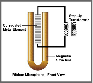
Ribbon Microphone
Corrugated Metal Element
= a metal band like in an accordion
Within dynamic microphones, we distinguish between voice coil microphones and ribbon microphones. The dynamic microphone is a voice coil type microphone, and the ribbon microphone therefore is regarded as a variant of the dynamic microphone.
The ribbon microphone was invented around 1920, where it quickly became popular within the movie and recording industry. Later on, it has become unfashionable, although its sound characteristics are excellent.
One of the great benefits of a ribbon microphone is that you can make recordings without the need of a power supply for the microphone. A ribbon mic will work without battery or phantom power, making this type of microphone much easier to use in the daily work.
The membrane of a ribbon microphone consists of a thin metallic strip or ribbon, which is suspended (folded like an accordion) between the poles of a permanent magnet. When speaking into the microphone, the ribbon moves correspondingly, in this way inducing (generating) a voltage in the ribbon.
The voltage is fed to the primary winding of a transformer within the microphone.
From the secondary winding, the signal is fed to an external mixer or amplifier.
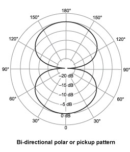
The ribbon microphone has got a hyper cardioid characteristic.
Ribbon Microphone
--------------------------------------------------
Condenser Microphone
A condenser microphone is in many ways like an reversed electrostatic speaker.
It consists of a thin metal membrane suspended close to a fixed (stationary) metal plate. The distance between the membrane and the metal plate is often below 0.5 mm.
From a battery or power supply direct current (DC) is fed to the two metal parts - membrane and plate. One part is positive loaded and the other part is negative loaded. The applied voltage, usually 24VDC or 48VDC, is called a "phantom power" because it is invisible like a phantom. The phantom power remains invisible inside the microphone and does not become visible, even if you speak into the microphone.
When the membrane is subjected to sound waves, it will move accordingly with the sound waves. The phantom power in this way is superimposed (mixed) with an alternating voltage (AC) from the membrane in accordance with the sound variations.
The alternating voltage (= the audio signal) is fed from the microphone (via capacitor C) (the capacitor blocks any DC, while letting AC pass), and is finally fed to the input of a mixer or amplifier.
Schallwellen = sound waves
Membran = membrane
Gegenelektrode = fixed metal plate
C = capacitor (to stop phantom power from disappering)
U = battery or power supply
R = resistor
The resistor is used to feed DC to the membrane,
without shorting (cancelling) the AC signal ("the sound").
Signal = output signal, sound signal
Masse = ground, minus
Line-In = microphone output
(from here, the signal is fed to a mixer or amplifier)
--------------------------------------------------
Electret Microphone
The electret microphone is a kind of condenser microphone, taking advantage of certain plastics without external influence ("spontaneous") generating electrical voltage. In this way, the microphone so to speak, has a built-in power supply.
Otherwise, the electret microphone works like a condenser microphone.
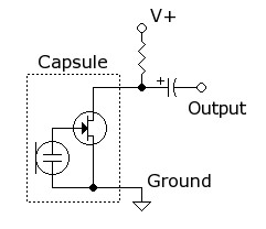
In the diagram below, a FET (transistor) is added to amplify the microphone signal.
Diagram showing the circuitry of an electret microphone.
The signal from the electret unit is amplified in the FET transistor.
The FET receives power (DC) from V+ via the resistor.
The size of the resistor is determining the gain and the output resistance.
The audio signal is taken out through the condenser.
Electret Microphone
--------------------------------------------------
Carbon Microphone
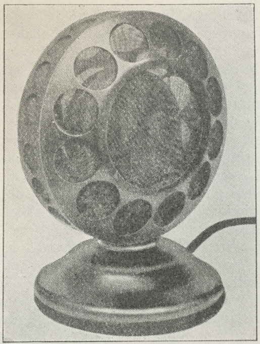
Western Electric carbon microphone from 1920
The carbon microphone is the earliest microphone type. It was developed for use in telephones.
The microphone consists of a small flat box, filled with carbon grains.
The box lid is a thin metal membrane, which is vibrating when hit by sound waves from someone who is speaking (or singing!).
In this way the carbon grains are compressed more or less, meaning that the electric resistance of the grains are changing or varying.
An electric current, which is sent through the carbon grains, is varying at the same rate as the sound vibrations received by the microphone.
From the above example we understand, that the carbon microphone needs an external power source to operate.
The frequency range of a carbon microphone is rather narrow: 200 - 2500 Herz.
Furthermore, the carbon microphone suffers from background noise and distortion, due to irregular changes in the carbon grains.
Let's also mention that further disadvantages include the fact, that the carbon microphone exhibits fluctuating sound sensitivity and distortion due to carbon grains which are often sticking together.
Despite all drawbacks, the carbon microphone is still in military use due to low weight, durability and a very high electrical output.
As already mentioned, the carbon microphone has got poor sound quality, and has gone out of use (apart possibly by the military).
Carbon Microphone
--------------------------------------------------
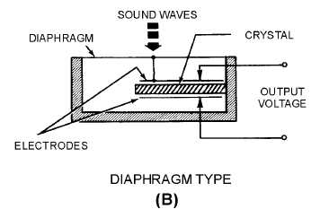
Crystal Microphone
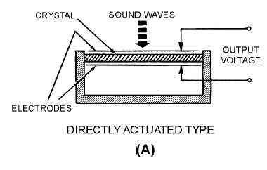
The crystal microphone is a microphone, where sound vibrations are affecting a piezoelectric crystal.
When sound vibrations are affecting a piezoelectric crystal, a voltage can be measured across the crystal. This voltage will vary according to the sound vibrations.
DiRECT COUPLED
The crystal is coupled in such a way that the sound waves hit the crystal directly.
iNDiRECT COUPLED
This type of microphone has a diaphragm
which is mechanically coupled to the crystal,
so that sound waves hit the crystal indirectly.
Shure 737A (crystal microphone)
--------------------------------------------------
--------------------------------------------------Piezoelectric effect
The piezoelectric effect (from Greek: piezein = squeeze or press) is a feature that many different kinds of crystals possess. If the crystal, for example, is pressed or squeezed, it reacts by forming an electrical voltage which can be measured on the crystal surface.
And vice versa:
If you charge a crystal with an electrical voltage, it changes its shape - small changes all right, but with a tremendous force.
The piezoelectric phenomenon was first demonstrated around 1880. Since then, crystals with this property have been used in many different contexts. From everyday life we could mention the "electronic" lighter where a piezoelectric crystal is hit by a hammer, in this way generating thousands of volts, which gets an electric spark to ignite.
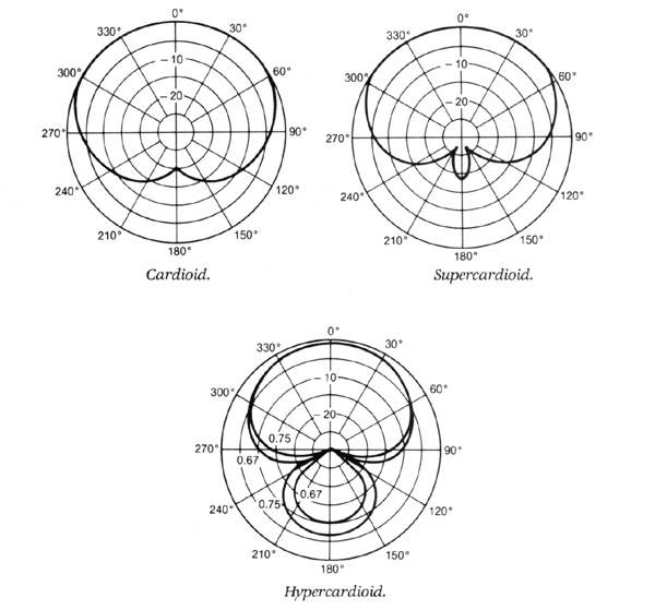
Pickup Patterns
A microphone may be more or less suitable for capturing sound from different directions. This ability is called pickup pattern. In a rock and jazz context, microphones with cardioid pattern are preferred:
- Cardioid
Cardioid is the most common characteristic of microphones. A cardioid microphone focuses on, what's right in front of the microphone, while it captures less from the surroundings.
- Super Cardioid
Super cardioid means further narrowing of the area that the microphone captures.
- Hyper Cardioid
As shown in the diagram below, a hyper cardioid microphone is even more sensitive than the super cardioid, but at the expense of penetrating sound from the rear side.
Here we see the cardioid patterne of three kidney types, Cardioid, Super Cardioid and Hyper Cardioid.
Imagine, that 0° is the point from which you are speaking into the microphone (on-axis).
--------------------------------------------------
Fiction & Fact
In this Shure, S-545 data sheet, you'll find fiction & fact on pick-up patterns of cardioid microphones.
++++++++++++++++++
FICTION: All "cardioid" microphones have similar pickup patterns.
FACT: In fact some so-called "cardioid" microphones actually pick up much sound from the rear at certain frequencies (particularly at low frequencies)! Others have side and rear pickup "lobes" at many erratically different frequencies. Some patterns are extremely "narrow" at high frequencies while being virtually omnidirectional (360° pickup) at critical low frequencies.
++++++++++++++++++
FICTION: All "cardioid" patterns are symmetrical about the axis.
FACT: Very few "cardioid" patterns are symmetrical about the axis in all planes. The pickup pattern in planes other than that for which cardioid data is published, often is not cardioid and actually is an undersirable pickup pattern. This can lead to all sorts of feedback problems from "floor bounce" and other reflected sounds. Test for pickup pattern symmetry by rotating the microphone while talking into it from various angles (45°, 90°) off-axis. Is the volume and tonal quality of the microphone consistent about the axis?
++++++++++++++++++
FICTION: The quality of sound is uniform with direction of pickup for all "cardioid" microphones.
FACT: A serious shortcoming of most "cardioids" is that off-axis pickup has markedly different tonal quality than on-axis pickup. Test for uniformity of tone by walking around the microphone placed on a stand and talking into it from various anqles. The volume should vary, but the tonal quality should not.
++++++++++++++++++
FICTION: the narrower the pickup pattern, the better the microphone performs.
FACT: Actually, for most cases the exact opposite is true. A very narrow pattern creates more problems than it solves in attempting to obtain good, uniform sound reproduction. Ideally, the REAR hemisphere rejection should be very great, while the front pickup should be both broad and uniform about the axis, and at all frequencies.
--------------------------------------------------
LiNKS
Microphone
--------------------------------------------------
The Music Scene of the 1960s:
--------------------------------------------------
This site is under constant consideration and expansion.
So, if you got an opinion on the topic in general or technical details in particular, don't hesitate to contact me:
Thank you very much!
Kurt Starlit
aka CykelKurt